A simpler version (Version 2.0) of the Aging-At-Home device is desirable to make
it faster and less complex to construct. Two videos show the assembly
process and the parts
required.
Here is the 4-minute DIY assembly process video:
Version 2.0 Build Process Video
Here is a video review of the parts required:
Version 2.0 Parts Review Video
Developing countries have fewer resources (tools, skilled workers, and
materials). So Version 2.0 of the device
can be constructed (making and assembling the parts) in about 30 minutes with
very limited mechanical skills required. Minimally, only a hack saw,
1/2 inch (12.7
mm) and 1/4 inch (6.3 mm) diameter drill bits, a knife, and two adjustable
wrenches are required.
Putting the parts
together takes only four minutes as shown in
the above "build process" video. There are fewer steps and parts required.
The operation of the device is the same (see videos page) although two
Velcro straps may be needed in Version 2.0 to fix the lever positions (see
the Version 1.0 parts and directions page about the Velcro strap's design) of a raised person
instead of one. The major three parts
are also the same. Only two
connector parts change (a Spring Link and an eye-bolt replace the
U-bolt connector) but less cutting and drilling is required.
There are three "connector" parts required - an eye-screw (one required),
an eye-hook (3 of them),
and Spring Links (two large, and either two small or two - 1 inch/25.4 mm dia. hose
clamps) are required.
Preparation
We prepared for assembly by doing the following 5 steps:
-
Cut using hack saw or chop saw with a metal blade the 7/8 in. (22.2 mm)
square steel tube to length (18 in. or 45.2 mm)
-
Drill 3 three 1/2 in. holes (12.7 mm) through the top and bottom
of the square tube in the middle and at the two ends (requires 0.5 in./12.7
mm
diameter metal drill bit).
Since these half inch holes are large holes, it may be easier to first drill 3 - 1/4 inch pilot
holes prior to drilling the three half inch holes.

-
Drill two .375 in. (9.53 mm) holes at the ends of
both orange load binder lever handles (see hole in handle)

3b. Alternate approach to step 3. above.
Since drilling holes in the 1/2 inch thick mild steel
composing the loadbinder's pull arm may be challenging for those without power
tools,
using a hose
clamp may be a viable alternative to save time and effort. Note that this
method may be less secure than the hole-drilling method. The pull rope
may be attached to the pull arm using a simple hose clamp:

Knot the rope and tighten a hose clamp around the rope and the pull arm end:

To eliminate sharp edges, wrap the hose clamp with electrical or other
tape.

-
Cut or grind the chrome metal hook off each of the two "rope ratchets"

-
Cut the two 1/2 inch (12.7 mm) diameter ropes (packaged with the
rope ratchets) in half (burning the nylon ends to stop them from fraying
is also desirable).
Assembly Process
Assembly:
This short
Video
shows how we constructed the device in about 4 minutes.
Here are the 7 steps shown in the video with explanations:
-
Bolt the orange ratchet load
binder to the eye screw (Note: the Eye Screw would normally be screwed
securely into a 2x6, 2x8 or 2x10 [inch] ceiling beam
[see illustration]
before doing this step):

-
Bolt the upper load binder to the lower load binder:

-
Bolt the lower load binder to the eye bolt that goes through the middle of
the square tube in step 4:

-
Put the 3 eye bolts in the 1/2 inch (12.7 mm) diameter holes in the bar. The "eyes" face down at
the ends and up in the middle. Securely tighten both nuts (non-locking and
locking) on the three Eye Bolts
as shown:

-
Connect the looped ends of the ropes to the brass Spring Hooks as shown:

-
Thread the ropes through the rope ratchets (Brass Spring Hooks go on the inside)
and knot the opposite ends of the ropes securely. Use the Large Spring Link to connect the end Eye
Bolts to the Rope Ratchets as shown:

-
Put the Small Spring Link(s) through hole in load binder(s) and thread the rope (the
half without the loop on its end) through
the Spring Link knotting it at the non-looped end (Note: using hose clamps to
attach the pull rope is
an alternative approach that is described in step 3b. above):
7b. - Alternative approach to step 7. above.
Knot the rope and tighten a hose clamp around the rope and the pull arm end
(Note: this eliminates the need to drill holes in the loadbinder arms):
The 5 Minor Parts
Eye Bolts are bolted to the cross-bar/square tube (one at middle [eye
points upward] and at two
ends [eyes point downward as shown in example (5) above].
The 3 Major Parts Discussion
-
The orange "lever load binders" or "chain binders"
shown below are commonly available because they are used by
freight haulers to tighten chains and stabilize loads on trailers.
But because of their simple design, metal workers in developing
countries may be able fabricate them if no commercial ones are available.

-
The "Rope Ratchets" are Part number 10030 "Pulley Hangers" with 8 feet of
1/2 in./12.7 mm dia. rope. Dimensions are 2 in./50.8 mm x 6.25 in./158.75
mm x 13.5 in./342.9 mm, Manufacturer:
Carolina North, Load Capacity: 500 lbs. ea., cost: $25.00 USD ea.
 Note also that parts such as the "rope ratchets"
could have substitutions that
perform the same function. Devices such "rope grabs", "rope clamps" and "ascenders" are used
by mountain climbers, window washers, and tree pruners (aborists).
Note also that parts such as the "rope ratchets"
could have substitutions that
perform the same function. Devices such "rope grabs", "rope clamps" and "ascenders" are used
by mountain climbers, window washers, and tree pruners (aborists).
All
use cam-based mechanisms to tighten (and loosen) ropes under considerable load mostly for
climbing, rappelling, and as tie-downs. See the Version 1.0 Parts and Directions
page for an alternative part to the "rope ratchets" if they are not available. One advantage of using the "rope ratchets"
is that they come with
ropes that are the proper size (diameter) and material which increases
safety.
-
The final major part is the 7/8 inch (22.2 mm) hollow, square, mild steel
tube (0.065 inch or 1.65 mm wall thickness although a thicker wall
would also be
acceptable)
which is
cut to 18 inches (457 mm) in length before drilling.
Disclaimer: Aging-At-Home.org claims no medical or engineering expertise,
and seeks only to share information we have found useful with others. Any
use of the information provided is up to others, and we assume no liability
for such use. This website is for information purposes only. This
information is not provided for the purpose of diagnosing, treating,
mitigating, or preventing any type of disease, disability, or medical
condition.
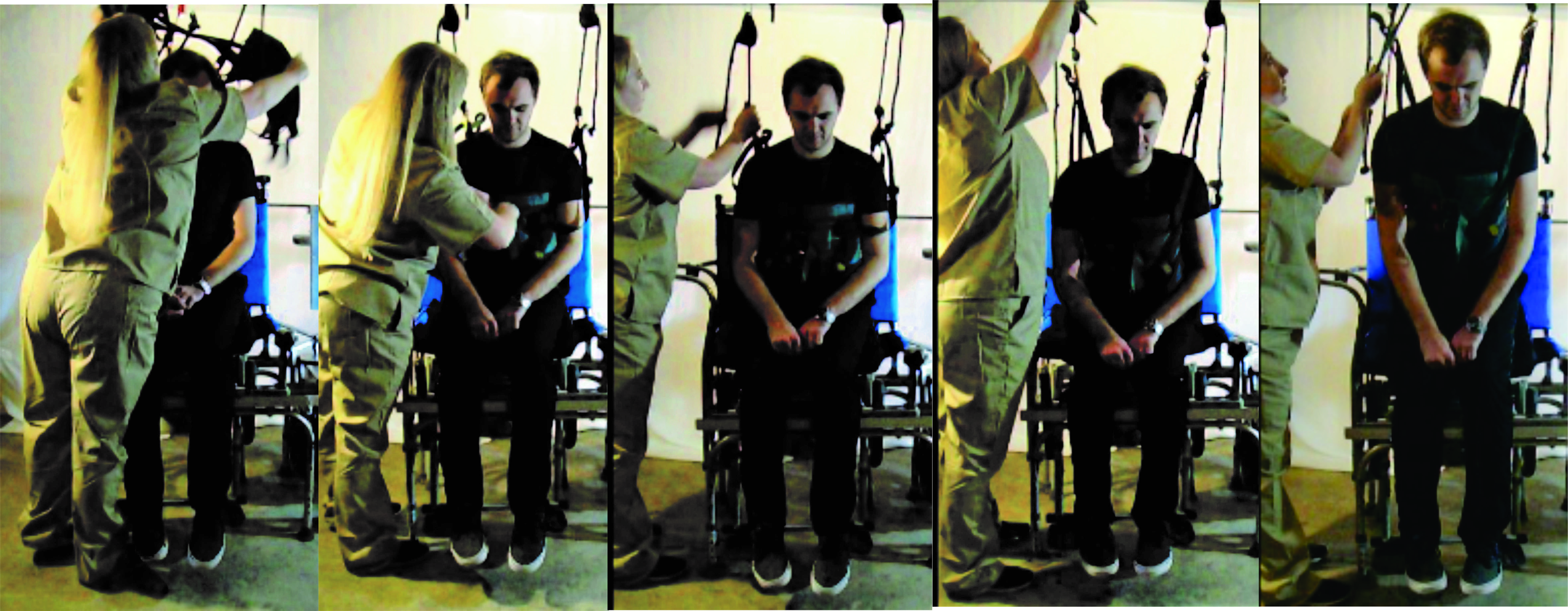
Next we will look at the device and site Demonstration Videos.
These videos are applicable to the operation of both V1.0 and V2.0.
To go to this page, click on the [ NEXT ] link below:
[ BACK ]
[ NEXT ]
home
|
basic design
|
V1.0 parts and directions
|
V2.0 parts and directions
|
videos
|
conclusion
Home
Copyright © 2022, Towersgreen, LLC
|